SMI Development
Support in Systems Engineering, Robotics and Vision, and Concept Realisation
SMI Development
Support in Systems Engineering, Robotics and Vision, and Concept Realisation
Systems Engineering
In a project with multiple stakeholders it is difficult to satisfy all demands. That is why Systems Engineering is paramount in achieving a balanced package of demands within the time to market and costs constrainsts.
SMI Development has years of experience in Systems Engineering and can help you develop a product that fulfills as many expectations as possible. Therefore, you are assured of the best fit for your project!
SMI Development distinguishes itself from other systems engineering offices by both the experience in complex government projects (tender) and product development in small businesses.
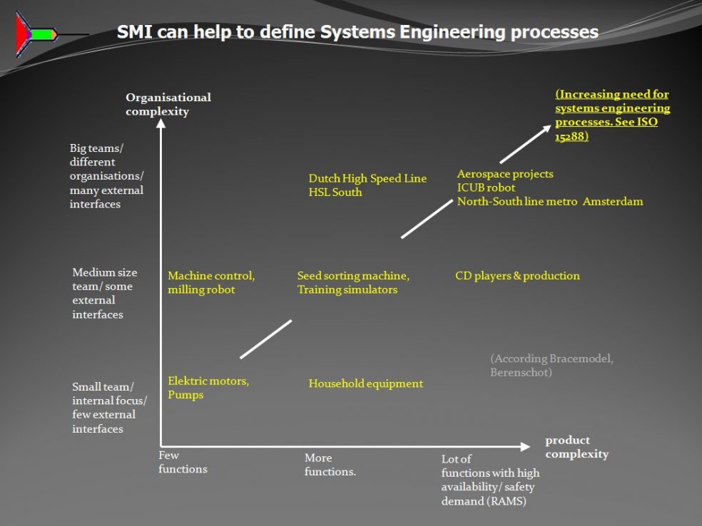
As you can see in the chart on the side, the application of Systems Engineering processes is determined by both organizational and product complexity. As the complexity increases, the application of systems engineering becomes more useful because the risk of cost overruns or failure to meet time to market increases. SMI can help you:
- To determine which systems engineering processes are useful and/or necessary.
Examples of systems engineering processes are:
- Configuration management
- Scheduling
- Validation and verification
- Risk management
- Design
- Requirement management - To plan and organize these processes.
- To do a structured product development within planning and time to market.
SMI has successfully contributed to the following projects in which (relatively) more Systems Engineering is/was needed:
- HSL South (Dutch train high speed train)
- Contracting and implementing North-South Line subway Amsterdam
- Tender processes RWS (20 year maintenance contract with all dutch water barriers Easter Scheld, Maeslant, Hartel, Hollandsche IJssel barrier)
- Seed sorting machine software (business name omitted due to contract clause).
- Simulators for aerospace and automobile manufacturer (business name omitted due to contract clause)
In addition, SMI employees taught Sales, CEO, managers and engineers how to write functional specifications (Mikrocentrum course for small business). A good specification (whether or not functional) is necessary to ensure that the system integrator gets what he expects.
Want to know how SMI Development can support your project? Please feel free to contact us for a cup of coffee and an exploratory conversation.
Systems Engineering

In a project with multiple stakeholders it is difficult to satisfy all demands. That is why Systems Engineering is paramount in achieving a balanced package of demands within the time to market and costs constrainsts.
SMI Development has years of experience in Systems Engineering and can help you develop a product that fulfills as many expectations as possible. Therefore, you are assured of the best fit for your project!
SMI Development distinguishes itself from other systems engineering offices by both the experience in complex government projects (tender) and product development in small businesses.
As you can see in the chart on the side, the application of Systems Engineering processes is determined by both organizational and product complexity. As the complexity increases, the application of systems engineering becomes more useful because the risk of cost overruns or failure to meet time to market increases. SMI can help you:
- To determine which systems engineering processes are useful and/or necessary. Examples of systems engineering processes are: - Configuration management - Scheduling - Validation and verification - Risk management - Design - Requirement management
- To plan and organize these processes.
- To do a structured product development within planning and time to market.
SMI has successfully contributed to the following projects in which (relatively) more Systems Engineering is/was needed:
- HSL South (Dutch train high speed train)
- Contracting and implementing North-South Line subway Amsterdam
- Tender process RWS (10 year maintenance contract Maeslantkering, Hartel and Hollandsche IJssel Kering)
- Seed sorting machine software (business name omitted due to contract clause).
- Simulators for aerospace and automobile manufacturer (business name omitted due to contract clause)
In addition, SMI employees taught courses how to write functional specifications for the Mikrocentrum (course for small businesses when and how to write a specification). A good specification (whether or not functional) is necessary in order to ensure that the system integrator gets what he expected.
Want to know how SMI Development can support your project? Please feel free to contact us for a cup of coffee and an exploratory conversation.
Robotics and vision
We are living in a changing world which will be increasingly be determined by robotics, domotics and artificial intelligence.
SMI Development can help you in developing your projects due to extensive experience in designing, simulation and programming of complex algorythms, electrotechnology and image recognition software.
People (and many animals) are very good at:
- Recognizing objects and faces
- Estimating how the backside of objects look
- Picking up and moving objects
- Respond quickly and accurately to unforeseen (unprogrammed) situations
Robots are becoming more and more successful in doing these human tasks. For example self-driving robots, cleaning robots, mowing robots, road worker robots or a weeding robot.
The SMI staff likes to help with innovative projects in robotics, aerospace and vision technology (see, eg. Jointmaster). SMI can help to distribute the work over partners and provide the system integration. SMI can also play a role in developing or judging potentially unrealistic requirements and functionalities because of extensive experience in:
- Software development
- 3D modeling
- Delivering proof of safety
- Recognition of faces and X-ray images (see Image Recognition Software)
Potentially unrealistic means that it is questionable whether the requirement or function can be fulfilled with the current state of technology. When others fail to provide the functionality or judge the requirement or function as unrealistic, we love to take a look at it!
To make a judgement in the design phase whether or not a solution exists for a set of functional requirements can be difficult. One methodology is simulation. Through extensive experience in simulation of moving and flying vehicles (see Dynamic System Design) with Matlab Simulink and Simscape Multibody (formerly SimMechanics), SMI can also assist in the verification of performance requirements for complex systems having people, tire models and electronics in the loop. For example: Is a tailless glider controllable under all conditions (and what does controllable exactly mean)? The results from the simulation models are also used to define and/or update new requirements for the subsystems that make up the design.
Robotics and Vision

We are living in a changing world which will be increasingly be determined by robotics, domotics and artificial intelligence.
SMI Development can help you in developing your projects due to extensive experience in designing, simulation and programming of complex algorythms, electrotechnology and image recognition software.
People (and many animals) are very good at:
- Recognizing objects and faces
- Estimating how the backside of objects look
- Picking up and moving objects
- Respond quickly and accurately to unforeseen (unprogrammed) situations
Robots are becoming more and more successful in doing these human tasks. For example self-driving robots, cleaning robots, mowing robots, road worker robots or a weeding robot.
The SMI staff likes to help with innovative projects in robotics, aerospace and vision technology (see, eg. Jointmaster). SMI can help to distribute the work over partners and provide the system integration. SMI can also play a role in developing or judging potentially unrealistic requirements and functionalities because of extensive experience in:
- Software development
- 3D modeling
- Delivering proof of safety
- Recognition of faces and X-ray images (see Image Recognition Software)
Potentially unrealistic means that it is questionable whether the requirement or function can be fulfilled with the current state of technology. When others fail to provide the functionality or judge the requirement or function as unrealistic, we love to take a look at it!
To make a judgement in the design phase whether or not a solution exists for a set of functional requirements can be difficult. One methodology is simulation. Through extensive experience in simulation of moving and flying vehicles (see Dynamic System Design) with Matlab Simulink and Simscape Multibody (formerly SimMechanics), SMI can also assist in the verification of performance requirements for complex systems having people, tire models and electronics in the loop. For example: Is a tailless glider controllable under all conditions (and what does controllable exactly mean)? The results from the simulation models are also used to define and/or update new requirements for the subsystems that make up the design.
Concept realisation

Launching a new product is a big challenge. The market has to be ready for and convinced by your innovation. Futhermore, your product needs to fully designed, developed for high reliability and safety.
SMI Development helps you in developing your product. From initial concept to the scaling of production. We will be by your side in every step of the process and we know that with our help you can overcome the greatest of challenges.
The concept phase determines around 80 % of the project future costs. The likelihood that the budget is exceeded or the planning runs behind schedule is increased by omissions in the concept phase. A few examples of possible omissions in the concept phase:
- Omitting important stakeholders or underestimating stakeholder needs
- Missing or inadequate RAMS requirements (Reliability, Availability, Maintainability, Safety)
- Omitting functional performance criteria
- Omitting verification and validation requirements
- Underestimating complexity
- Badly chosen or undefined interfaces with cooperating partners
Therefore, a successful concept phase is important to avoid a failed product launch. Statistically, 40-90% of all products cease to exist within 12 months after they have been introduced.
SMI Development helped to develop several products that still exist. See eg. The Joint Master (cheap DIY 2D and 3D milling) and Image Recognition Software.
SMI has also helped (after the concept phase......) government projects with huge cost overruns that were considered more or less failed. E.g. the Dutch High Speed Line HSL-South with unused Italian high speed trains. Because a government must tender (European legislation), it is important to pay very close attention to good functional specifications with well written RAMS criteria. After contracting, it is paramount for the government to fill in the role of system integrator.
SMI recommends that system integrator / systems engineer is positioned more firmly in large, complex projects.
SMI Development can help by actively supporting the design concept phase, fill in the role of system integrator or by doing a review on specifications/ writing the specifications.
Concept realisation

Launching a new product is a big challenge. The market has to be ready for and convinced by your innovation. Futhermore, your product needs to fully designed, developed and understood.
SMI Development helps you in developing your product. From initial concept to the scaling of production. We will be by your side in every step of the process and we know that with our help you can overcome the greatest of challenges.
The concept phase determines around 80 % of the project future costs. The likelihood that the budget is being exceeded or the planning runs behind schedule is increased by omissions in the concept phase. A few examples of possible omissions in the concept phase:
- Omitting important stakeholders or underestimating stakeholder needs
- Missing or inadequate RAMS requirements (Reliability, Availability, Maintainability, Safety)
- Omitting functional performance criteria
- Omitting verification and validation requirements
- Underestimating complexity
- Badly chosen or undefined interfaces with cooperating partners
Therefore, a successful concept phase is important to avoid a failed product launch. Statistically, 40-90% of all products cease to exist within 12 months after they have been introduced.
SMI Development helped to develop several products that still exist. See eg. The Joint Master (cheap DIY 2D and 3D milling) and Image Recognition Software.
SMI has also helped (after the concept phase) government projects with huge cost overruns that are considered more or less failed. E.g. the Dutch High Speed Line HSL-South with unused Italian high speed trains. Because a government must tender (European legislation), it is important to pay very close attention to good functional specifications with well written RAMS criteria. After contracting, it is paramount for the government to fill in the role of system integrator.
SMI recommends that the government/politics do position the role of system integrator / systems engineer more firmly in large, complex projects. This is because politicians, jurists, economists and engineering CEO’s (having non-project goals) dominate the places where important decisions are made. SMI Development can help by actively supporting the design concept phase, fill in the role of system integrator or by doing a review on specifications.
Skills
Skills
Systems Engineering (ISO 15288)
Delphi, C/C++, PHP, SQL, embedded systems
Writing Functional Specifations
aeroplane design, Load, Stress and FEM calculations
RAMS (Reliability, Availability, Maintainability, Safety), SIL, fault trees, FMEA
Interface en requirements management
Image recognition
Concept design & Product development
SYSTEMS ENGINEERING (ISO 15288)
DELPHI, C/C++, PHP, SQL, EMBEDDED SYSTEMS
WRITING FUNCTIONAL SPECIFATIONS
AEROPLANE DESIGN
DESIGN AND DEVELOPING SAFETY FEATURES
INTERFACE EN REQUIREMENTS MANAGEMENT
IMAGE RECOGNITION
CONCEPT DESIGN & PRODUCT DEVELOPMENT
Portfolio
 SMI Development helps Goodlife Design BV to design and produce a product that enables the end-user to create mortise tenon wood joints + 3D milling objects created in Blender.Jointmaster
 SMI Development helped a company to sort objects (information is not specific because of non-disclosure agreement) using image recognition techniques. Currently the software is sorting 300.000 objects per day.Image recognition software
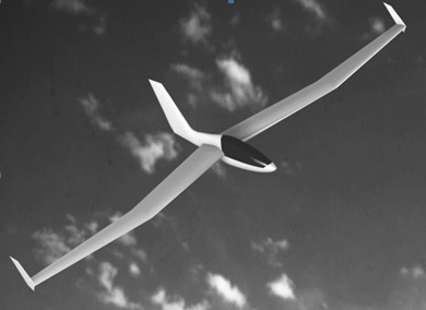 SMI Development developed software to design a tailless glider having gull shaped wings. The software is used throughout the product life cycle to investigate the effect of design decisions on functional performance.Tailless glider design
SMI Development has helped Goodlife Design BV to design a automatic finger joint machine. The finger joint machine's main function is to enable the end-user to create very precise (mortise tenon) wood joints. The end-user can use either his mobile phone or a Windows computer to control the finger joint jig.

The end-user only needs a table saw and the finger joint jig to create the wood connections. The end-user can either create the finger joint jig himself or buy a pre-assembled jig on the Jointmaster website.

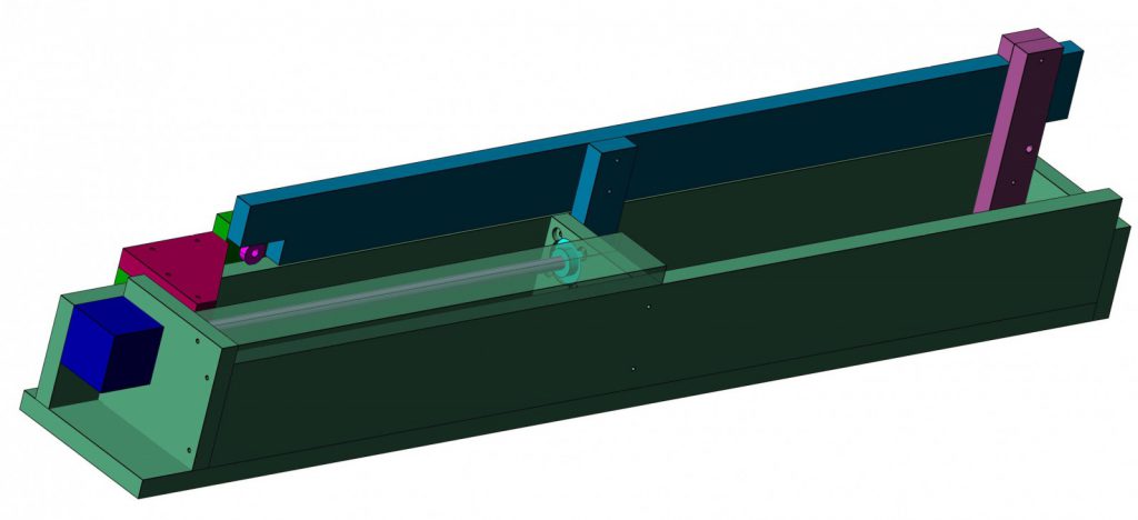
The finger joint jig moves by means of a step-motor (shown as the dark blue component in the figure above).
The end-user can choose whether he prefers: • The simplest solution using Jointmaster Audio. The stepmotor is driven by means of the audio signal from the stereo output of the mobile phone or computer. • A more advanced solution using Toothmaster. This is a wireless solution using Bluetooth. Runs only on Android devices. • The most advanced solution using Jointmaster Pro. Jointmaster pro is connected using USB to a Windows computer and also offers 3D milling by means of a GCode interpreter (The Gcode interpreter is part of Jointmaster Pro). A 3D milling product can run for a couple of days having 20.000-100.000 lines of Gcode. For this reason Jointmaster Pro has to be extremely reliable to prevent ruined milling products. XML Commands are communicated from the Windows computer to a STM32 discovery board. Every command has a unique identifier. In case of packet loss, the STM32 requests the lost packets from the Windows application. Commands sent from the Windows application to the STM32 are buffered to reach highest throughput. The STM32 discovery board monitors limit/kill switches and immediately stops processing if limit/kill switch is hit. The limit/kill switches are also used to return to start position.
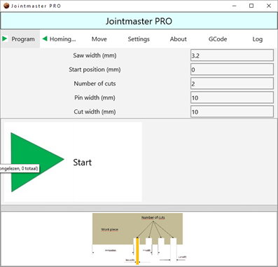 SMI programmed the Jointmaster USB and Audio solution in Delphi XE. The STM32 discovery is programmed in C. SMI helped Goodlife to connect with Chinese suppliers in order to have the best price to quality ratio components (step motor, step motor driver, power supply and bearings).
SMI helped a company (non-specified due to non-disclosure agreement) to create image recognition software to sort objects based on roentgen pictures . The software runs on Windows platforms in a scalable architecture. By adding more Windows platforms, more items can be sorted. The software is derived from image recognition software used to detect finger prints or faces utilizing a so called graph database. The object are then sent to a sorting robot.
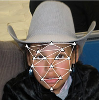
The image recognition software contains several modules:
- Roentgen picture module:
- Communicates pictures to the controller module.
- Takes a picture upon command from the controller module.
- Communicates with the roentgen camera and enables several camera options to be set like binning, resolution, image position and size, and the number of pictures to average upon.
- Standardizes the picture by means of so-called offset and flat field correction.
- Extraction module:
- Module to extract and sort objects.
- This module places the roentgen pictures at a specific folder.
- The extraction module recognizes the objects in the picture and sends results back to the controller.
- Sorting robot controller:
- Module to control the sorting robot and other modules.
- Database optimalization module
- Module to optimize the graph database.
- Has a Client-Server architecture.
- Several people can work concurrently to optimize multiple databases.
- Designed the software in close cooperation with other stakeholders.
- Wrote the interface specifications to other machine parts.
- Wrote and maintains the software in Delphi.
- Wrote the manuals for the operators.
- Trained the operators to use the software
The aerodynamic design of the FAI standard class competition glider has been constantly refined during the past decades. With a glide ratio of 1:43 and a minimum sink rate of 0.58 m/sec, however, the aerodynamic refinement of this type of glider seems to have reached its limits and further substantial gains in performance are not to be expected.
Some years ago the idea came up that perhaps a tailless glider would be capable of a higher performance. By omission of the horizontal tailplane and the tailboom, the tailless glider could be given a smaller wetted area, a lower weight and a higher aspect ratio wing.
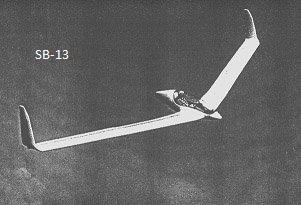
Akaflieg Braunschweig, a student driven flying club in Germany, constructed a tailless glider with a constant chord aft swept wing in 1988, called SB13.
This SB-13 (see picture below) had a glide ratio of 42, a rather high empty weight, some undesirable dynamic modes and difficult flying characteristics.
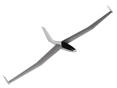
In 1994 Mr. B.F. Seffinga of the Delft Aerospace university made a preliminary design of the gull winged DUTAG glider (Delft University of Technology Advanced Glider, see picture below). By using this type of planform together with detailed aeroelastic tailoring the glider could be given the desired flying characteristics. Ir. M.Wittebrood graduated on the DUTAG subject and is currently a SMI Development partner.
In the M.Wittebrood thesis, it was proven that:
- The DUTAG concept needs a small horizontal stabiliser to get ahead of FAI standard class competition.
- The DUTAG concept has some dangerous inverted pilot control actions in certain situations.
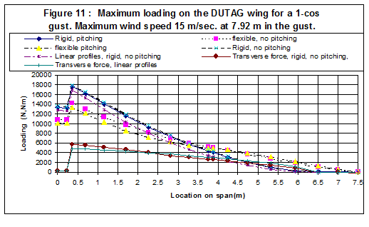
- The DUTAG concept offers very good so-called gust alleviation. This results into lower bending moments in the aeroplane wing(see graph below) and (after some design iterations) to lower aeroplane mass.
SMI decided to fund the development of tailless aircraft design software and make it freely available (please fill in the contact form at bottom of the website) in the hope that others can help to make it more useful.
Designing tailless flexible aircraft is difficult because all design parameters influence each other and the resulting influence on overall aircraft performance:
- Wing bending and torsion leads to different aerodynamic forces.
- Wing bending and torsion is caused by the aerodynamic forces.
- The aeroplane flies due to the aerodynamic forces and if they change due to wing loading, the flight path is different.
- The pilot is also acting upon the changed flight path and thus changes the aerodynamic forces.
- The aeroplane mass has to be minimized given the pilot weight, design regulations and maximum wing span (15 m) in the FAI standard class.
- A glider has to perform under different weather conditions. If there is a lot of rising air, gliders fly with water to reach high speed. The maximum amount of water is around 50 % of aeroplane empty weight.
- A heavier glider needs more wing surface. More wing surface means more weight etc.
Several software modules were created to make a fast design iterations possible:
- NUR module (NUR fur die NURflugel) The backbone of the NUR module is a simplified FEM (Finite Element Method) computer model (only beam and mass elements are used) that is given the same aerodynamic and structural properties as the real aircraft. This simulated model is not static, it can move and accelerate in any direction under the influence of the acting airloads, mass loads and reaction loads. In this way the NUR module can be used for flight path, motion and mission simulation.
During the simulation the module calculates all airloads, accelerations, mass loads and reaction loads on every part of the flexible aircraft. The attitude of the aircraft with respect to the gravity field is taken into account. The actual mass and stiffness distributions of the aircraft in a specific design phase are used.
The flight path simulation is used to check the performance, stability and control as well as the operational limits of the aircraft. The flight path simulation is also used to find the dynamic limit loads on the flexible and trimmed aircraft during take off, climb, cruise, maneuvering, gust, approach and landing. In the NUR module this process is completely automated.The NUR module is used in three different modes :- Rigid: No aeroelastic effects are taken into account. Only static flight cases.
- Flexible: Aeroelastic effects incorporated. Only static flight cases.
- Free flying : The flexible airplane is flying in time space. Gust and dynamic behavior can be investigated.
The NUR module makes use of lifting line theory in combination with strip theory to calculate the aerodynamics. To make the time response possible the program makes use of modal residualization. The aerodynamics used are quasi-stationary, thus the module can only predict flutter at low speeds with low frequency(max. 40 Hz).
- Spar module This module calculates the stiffnesses of the local wing and fuselage sections by means of the thin membrane and engineer bending theory.The local stiffnesses are used inside the NUR module beam model. All local sections are saved in a database for further processing. The loading on the wing that is calculated by the NUR module is returned to the Spar module to calculate the shear and normal flows. These flows can be put into a panel buckling program to check for local buckling in the concept phase. Creating a FEM model to do these calculations would make the design process far to sluggish in the concept phase.
- Mass module Changes in lay-up for the local sections are given to the mass module to recalculate the mass distribution. The mass distribution is related to the most important parameters that define the wing planform. This means that planform changes can easily be accomplished
In order to make short design iterations possible (necessary to check all constraints and requirements) more modules are necessary. For example the already mentioned panel buckling program or 2D/3D aerodynamic modules. Please contact SMI for more information or help designing your aeroplane.
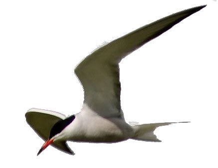
SMI is currently helping with the TERN-02 aeroplane design. This almost tailless model aeroplane will have a small trimmable elevator and will use flapping wing propulsion like real terns.
 SMI Development helped various companies to design dynamic systems. To verify high level functional performance, dynamic models (like car tire suspension model) are necessary.Dynamic System Design
 SMI Development helped RWS (RijksWaterStaat) and Prorail to create the so-called integral safety case. The Integral Safety Case proves that the HSL-South can be safely used.HSL-South (Dutch High Speed Line)
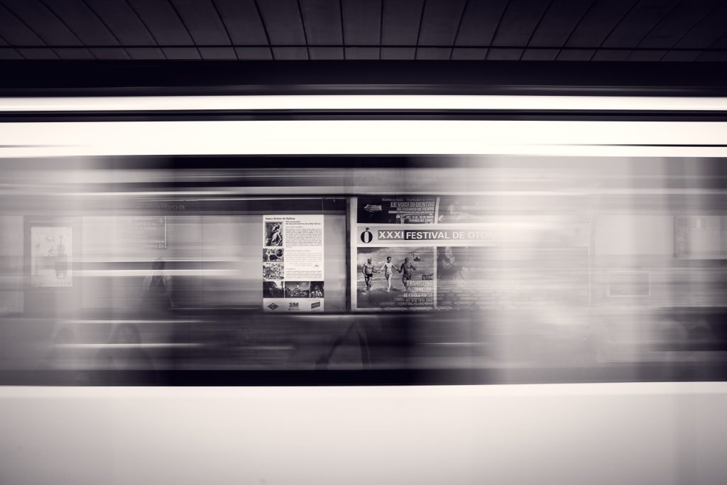 SMI Development helped North-South line project management to appreciate and implement system engineering processes.North-South line (Metro Amsterdam)
SMI can help you build a design performance model to verify functional requirements. Combined with SMI’s experience in designing dynamic systems it will be possible to estimate the technical feasibility of a project.
Development engineers were already involved in dynamic system design for several projects:
- Load calculations for the design and development of a Zeppelin. Rigid Airship design, Lelystad

Knowledge for designing and building a zeppelin was either lost or could no longer be used due to changed legislation. For example the following would not be acceptable nowadays:
- The Hindenburg used hydrogen to keep it floating. Hydrogen is highly flammable.
- The skin was highly flammable.
- Building the Hindenburg was done on 50 meter high stairs.
For this reason the Rigid Airship had to be redesigned using new materials, leading to a different mass distribution and different loads on the airship.
The most extreme scenarios an airship has to withstand are nowadays prescribed by JAR/ FAR legislation. For this reason a dedicated simulation and mass program (written in Delphi) were created to calculate loads on the airship in the most extreme conditions. Failing to test against an extreme scenario in the initial design phase will lead to very high costs in a later phase or a failed project because:
- All detail drawings have to be redone.
- All load and stress calculations have to be redone. This can lead to a lot of design iterations.
- Moulds and jigs have to be modified.
- The original planning will most likely be pushed back.
- One of SMI Development engineers programmed Fokker 100 flight simulator software in C++ for a research institute (company name omitted due to non-disclosure agreement). The software generates realistic accelerations in the Fokker 100 cabin by means of a Fokker 100 simulation data package. The Fokker 100 cabin moves on top of a so-called hexapod. A check model for the Fokker 100 engine was made in Matlab Simulink to validate the complex engine model source code.
- SMI engineers participated in a feasibility study to design/ develop a car simulator (Company name omitted due to non-disclosure). A simulation model was created using Matlab-Simulink and Simscape multibody to verify a number of critical performance parameters. The Simulation involved simulating a driving vehicle on 4 tires using TNO tire model. For an example please watch this video.
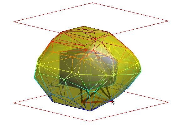
- One SMI engineer performed envelope calculations for the design and optimization of hexapod simulators. The simulator envelope is used to design the amount of space in the flight simulator building. See picture below for a cabin (blue inside envelope) on top of hexapod with envelope (yellow).
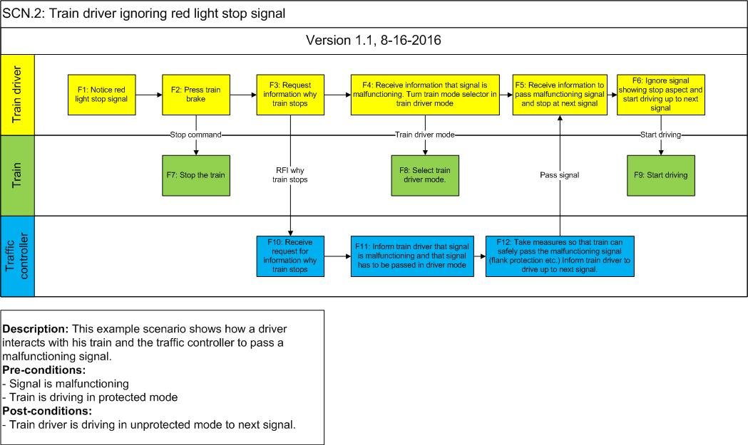 We created around 300 scenarios in a tool called CORE (for a simple example scenario, see “Train driver ignoring red light signal stop” scenario above, real scenario’s can have several stakeholders and interacting systems containing 100-200 functions).All scenarios contained the functions on the interfaces between parties. A FMEA (Failure Mode Effect Analysis) was conducted on all functions in the scenarios. The identified hazards were mitigated by the involved parties (by pointing into the lower level safety cases) or were mitigated by building new systems and procedures. ProRail did not have any experience in exploiting a high speed line nor did it have any experience with ETCS or ERTMS (European Train Control System). For this reason we helped ProRail to create new procedures where needed. The following parties play a role in the created scenarios:
- Infraspeed, responsible for designing, building, and maintaining HSL-South
- Prorail VL, responsible for route setting on HSL-South
- Prorail SMC, responsible for providing power to HSL-South
- NS Hispeed, responsible for driving high speed trains on HSL-South
- Fire brigade, responsible for evacuation
- Water authorities, responsible for protecting the dikes
- m.wittebrood@smidev.nl
- +31(0)618568268
- Gildeweg 16-1, 4383 NK, Vlissingen, the Netherlands
Amsterdam Metro and Tram is responsible for building and maintaining the Amsterdam subway and tram system. SMI Development has helped Amsterdam Metro and Tram by writing detailed tenders and in supporting existing tenders for several large maintenance projects. SMI also helped in writing the tender for the expansion of the existing system with a new line, the North-South line. While contractors perform the contracted activities, the existing subway system had to remain in operation with a high availability.
The individual contracts are managed by the Amsterdam Metro and Tram contract teams. The individual contracts are not perfect and have to be modified in case of missing requirements, scope or interface problems. The System Integration team has to bridge the gaps between the contract teams and other stakeholders.
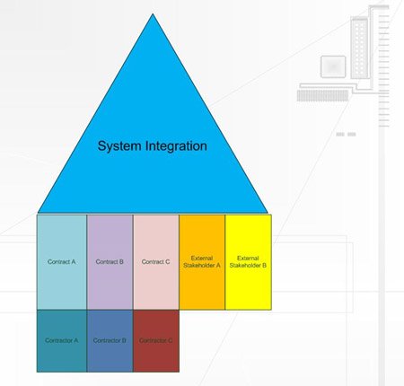
One SMI engineer was RAMS (Reliability, Availability, Maintenance, Safety) and scenario specialist in the system integration team during the contract and building phase. The subway system has a high availability (99.7 %). The RAMS engineer did budget the needed availability over the several contracts in the contract phase and verified the RAMS documentation supplied by the contractors in the design phase.
The large maintenance related projects and North-South line expansion have several components:- North-South line contract to install all systems on the North-South line. The North-South line systems have to be connected to the existing and new interfacing systems. The North-South line contract is build only, without maintainenance. All other contracts are a combination of design, build, and maintainenance contracts.
- Modernization of existing metro tubes with safety systems for successful evacuation in case of fire. Scenarios include fires originating in the metro, technical rooms, the tubes, and the platform.
- Full replacement of the current signaling and control system with a new system. The signaling and control system keeps trains at a safe distance and sets automatic routes according to the predefined time table.
- Replacing depreciated metro trains with modern trains. The remaining fleet of existing metro trains had to be modified to be able to interact with the new signaling and control system.
- Full replacement of the current system control system with a new system. The system control system consists of several components (all of which are separate contracts):
- Entrance gates control system which includes the payment system
- Camera surveillance system
- Traction control system (DC and high voltage AC switching)
- Fire fighting installations
- Emergency systems
- Public Announcement system
The contracts are so-called functional specifications with a rewards and penalties on RAM (Reliability, Availability, Maintenance) parameters. To specify the functions and interfaces to contract, scenario analysis with all parties involved is crucial.
SMI also helped by creating plans how Systems Engineering (ISO-15288) processes could be used by Amsterdam Metro and Tram and the System Integration team during the building phase:
- Plan to attach the design process to planning process
- Plan to have 6 different perspectives on the future (requirements view, functional view, physical view etc.). These views form the shared design space for all involved parties (including Amsterdam Metro and Tram, contractors, and external stakeholders). Please note that there is more risk (planning, cost) when these perspectives are missing because interfaces will not match. This is due to the fact that when a central view is missing, every stakeholder will form his personal view on the design reality. If interfaces do not match, there is a high risk that planning will not be met.
SMI can also help you to write plans which reduce risk.
Portfolio
(Tap on tiles for summary information)
 SMI Development helps Goodlife Design BV to design and produce a product that enables the end-user to create mortise tenon wood joints + 3D milling objects created in Blender.Jointmaster
SMI Development has helped Goodlife Design BV to design a automatic finger joint machine. The finger joint machine's main function is to enable the end-user to create very precise (mortise tenon) wood joints. The end-user can use either his mobile phone or a Windows computer to control the finger joint jig.

The end-user only needs a table saw and the finger joint jig to create the wood connections. The end-user can either create the finger joint jig himself or buy a pre-assembled jig on the Jointmaster website.

The finger joint jig moves by means of a step-motor (shown as the dark blue component in the figure above).
The end-user can choose whether he prefers: • The simplest solution using Jointmaster Audio. The stepmotor is driven by means of the audio signal from the stereo output of the mobile phone or computer. • A more advanced solution using Toothmaster. This is a wireless solution using Bluetooth. Runs only on Android devices. • The most advanced solution using Jointmaster Pro. Jointmaster pro is connected using USB to a Windows computer and also offers 3D milling by means of a GCode interpreter (The Gcode interpreter is part of Jointmaster Pro). A 3D milling product can run for a couple of days having 20.000-100.000 lines of Gcode. For this reason Jointmaster Pro has to be extremely reliable to prevent ruined milling products. XML Commands are communicated from the Windows computer to a STM32 discovery board. Every command has a unique identifier. In case of packet loss, the STM32 requests the lost packets from the Windows application. Commands sent from the Windows application to the STM32 are buffered to reach highest throughput. The STM32 discovery board monitors limit/kill switches and immediately stops processing if limit/kill switch is hit. The limit/kill switches are also used to return to start position.
 SMI programmed the Jointmaster USB and Audio solution in Delphi XE. The STM32 discovery is programmed in C. SMI helped Goodlife to connect with Chinese suppliers in order to have the best price to quality ratio components (step motor, step motor driver, power supply and bearings).
 SMI Development helped a company to sort objects (information is not specific because of non-disclosure agreement) using image recognition techniques. Currently the software is sorting 300.000 objects per day.Image recognition software
SMI helped a company (non-specified due to non-disclosure agreement) to create image recognition software to sort objects based on roentgen pictures . The software runs on Windows platforms in a scalable architecture. By adding more Windows platforms, more items can be sorted. The software is derived from image recognition software used to detect finger prints or faces utilizing a so called graph database. The object are then sent to a sorting robot.

The image recognition software contains several modules:
- Roentgen picture module:
- Communicates pictures to the controller module.
- Takes a picture upon command from the controller module.
- Communicates with the roentgen camera and enables several camera options to be set like binning, resolution, image position and size, and the number of pictures to average upon.
- Standardizes the picture by means of so-called offset and flat field correction.
- Extraction module:
- Module to extract and sort objects.
- This module places the roentgen pictures at a specific folder.
- The extraction module recognizes the objects in the picture and sends results back to the controller.
- Sorting robot controller:
- Module to control the sorting robot and other modules.
- Database optimalization module
- Module to optimize the graph database.
- Has a Client-Server architecture.
- Several people can work concurrently to optimize multiple databases.
- Designed the software in close cooperation with other stakeholders.
- Wrote the interface specifications to other machine parts.
- Wrote and maintains the software in Delphi.
- Wrote the manuals for the operators.
- Trained the operators to use the software
 SMI Development developed software to design a tailless glider having gull shaped wings. The software is used throughout the product life cycle to investigate the effect of design decisions on functional performance.Tailless glider design
The aerodynamic design of the FAI standard class competition glider has been constantly refined during the past decades. With a glide ratio of 1:43 and a minimum sink rate of 0.58 m/sec, however, the aerodynamic refinement of this type of glider seems to have reached its limits and further substantial gains in performance are not to be expected.
Some years ago the idea came up that perhaps a tailless glider would be capable of a higher performance. By omission of the horizontal tailplane and the tailboom, the tailless glider could be given a smaller wetted area, a lower weight and a higher aspect ratio wing.
Akaflieg Braunschweig, a student driven flying club in Germany, constructed a tailless glider with a constant chord aft swept wing in 1988, called SB13.
This SB-13 (see picture below) had a glide ratio of 42, a rather high empty weight, some undesirable dynamic modes and difficult flying characteristics.

In 1994 Mr. B.F. Seffinga of the Delft Aerospace university made a preliminary design of the gull winged DUTAG glider (Delft University of Technology Advanced Glider, see picture below). By using this type of planform together with detailed aeroelastic tailoring the glider could be given the desired flying characteristics. Ir. M.Wittebrood graduated on the DUTAG subject and is currently a SMI Development partner.

In the M.Wittebrood thesis, it was proven that:
- The DUTAG concept needs a small horizontal stabiliser to get ahead of FAI standard class competition.
- The DUTAG concept has some dangerous inverted pilot control actions in certain situations.
- The DUTAG concept offers very good so-called gust alleviation. This results into lower bending moments in the aeroplane wing(see graph below) and (after some design iterations) to lower aeroplane mass.

SMI decided to fund the development of tailless aircraft design software and make it freely available (please fill in the contact form at bottom of the website) in the hope that others can help to make it more useful.
Designing tailless flexible aircraft is difficult because all design parameters influence each other and the resulting influence on overall aircraft performance:
- Wing bending and torsion leads to different aerodynamic forces.
- Wing bending and torsion is caused by the aerodynamic forces.
- The aeroplane flies due to the aerodynamic forces and if they change due to wing loading, the flight path is different.
- The pilot is also acting upon the changed flight path and thus changes the aerodynamic forces.
- The aeroplane mass has to be minimized given the pilot weight, design regulations and maximum wing span (15 m) in the FAI standard class.
- A glider has to perform under different weather conditions. If there is a lot of rising air, gliders fly with water to reach high speed. The maximum amount of water is around 50 % of aeroplane empty weight.
- A heavier glider needs more wing surface. More wing surface means more weight etc.
Several software modules were created to make a fast design iterations possible:
- NUR module (NUR fur die NURflugel) The backbone of the NUR module is a simplified FEM (Finite Element Method) computer model (only beam and mass elements are used) that is given the same aerodynamic and structural properties as the real aircraft. This simulated model is not static, it can move and accelerate in any direction under the influence of the acting airloads, mass loads and reaction loads. In this way the NUR module can be used for flight path, motion and mission simulation.
During the simulation the module calculates all airloads, accelerations, mass loads and reaction loads on every part of the flexible aircraft. The attitude of the aircraft with respect to the gravity field is taken into account. The actual mass and stiffness distributions of the aircraft in a specific design phase are used.
The flight path simulation is used to check the performance, stability and control as well as the operational limits of the aircraft. The flight path simulation is also used to find the dynamic limit loads on the flexible and trimmed aircraft during take off, climb, cruise, maneuvering, gust, approach and landing. In the NUR module this process is completely automated.The NUR module is used in three different modes :- Rigid: No aeroelastic effects are taken into account. Only static flight cases.
- Flexible: Aeroelastic effects incorporated. Only static flight cases.
- Free flying : The flexible airplane is flying in time space. Gust and dynamic behavior can be investigated.
The NUR module makes use of lifting line theory in combination with strip theory to calculate the aerodynamics. To make the time response possible the program makes use of modal residualization. The aerodynamics used are quasi-stationary, thus the module can only predict flutter at low speeds with low frequency(max. 40 Hz).
- Spar module This module calculates the stiffnesses of the local wing and fuselage sections by means of the thin membrane and engineer bending theory.The local stiffnesses are used inside the NUR module beam model. All local sections are saved in a database for further processing. The loading on the wing that is calculated by the NUR module is returned to the Spar module to calculate the shear and normal flows. These flows can be put into a panel buckling program to check for local buckling in the concept phase. Creating a FEM model to do these calculations would make the design process far to sluggish in the concept phase.
- Mass module Changes in lay-up for the local sections are given to the mass module to recalculate the mass distribution. The mass distribution is related to the most important parameters that define the wing planform. This means that planform changes can easily be accomplished
In order to make short design iterations possible (necessary to check all constraints and requirements) more modules are necessary. For example the already mentioned panel buckling program or 2D/3D aerodynamic modules. Please contact SMI for more information or help designing your aeroplane.
SMI is currently helping with the TERN-02 aeroplane design. This almost tailless model aeroplane will have a small trimmable elevator and will use flapping wing propulsion like real terns.

 SMI Development helped various companies to design dynamic systems. To verify high level functional performance, dynamic models (like car tire suspension model) are necessary.Dynamic System Design
SMI can help you build a design performance model to verify functional requirements. Combined with SMI’s experience in designing dynamic systems it will be possible to estimate the technical feasibility of a project.
Development engineers were already involved in dynamic system design for several projects:
- Load calculations for the design and development of a Zeppelin. Rigid Airship design, Lelystad

Knowledge for designing and building a zeppelin was either lost or could no longer be used due to changed legislation. For example the following would not be acceptable nowadays:
- The Hindenburg used hydrogen to keep it floating. Hydrogen is highly flammable.
- The skin was highly flammable.
- Building the Hindenburg was done on 50 meter high stairs.
For this reason the Rigid Airship had to be redesigned using new materials, leading to a different mass distribution and different loads on the airship.
The most extreme scenarios an airship has to withstand are nowadays prescribed by JAR/ FAR legislation. For this reason a dedicated simulation and mass program (written in Delphi) were created to calculate loads on the airship in the most extreme conditions. Failing to test against an extreme scenario in the initial design phase will lead to very high costs in a later phase or a failed project because:
- All detail drawings have to be redone.
- All load and stress calculations have to be redone. This can lead to a lot of design iterations.
- Moulds and jigs have to be modified.
- The original planning will most likely be pushed back.
- One of SMI Development engineers programmed Fokker 100 flight simulator software in C++ for a research institute (company name omitted due to non-disclosure agreement). The software generates realistic accelerations in the Fokker 100 cabin by means of a Fokker 100 simulation data package. The Fokker 100 cabin moves on top of a so-called hexapod. A check model for the Fokker 100 engine was made in Matlab Simulink to validate the complex engine model source code.
- SMI engineers participated in a feasibility study to design/ develop a car simulator (Company name omitted due to non-disclosure). A simulation model was created using Matlab-Simulink and Simscape multibody to verify a number of critical performance parameters. The Simulation involved simulating a driving vehicle on 4 tires using TNO tire model. For an example please watch this video.
- One SMI engineer performed envelope calculations for the design and optimization of hexapod simulators. The simulator envelope is used to design the amount of space in the flight simulator building. See picture below for a cabin (blue inside envelope) on top of hexapod with envelope (yellow).

 SMI Development helped RWS (RijksWaterStaat) and Prorail to create the so-called integral safety case. The Integral Safety Case proves that the HSL-South can be safely used.HSL-South (Dutch High Speed Line)
 We created around 300 scenarios in a tool called CORE (for a simple example scenario, see “Train driver ignoring red light signal stop” scenario above, real scenario’s can have several stakeholders and interacting systems containing 100-200 functions).All scenarios contained the functions on the interfaces between parties. A FMEA (Failure Mode Effect Analysis) was conducted on all functions in the scenarios. The identified hazards were mitigated by the involved parties (by pointing into the lower level safety cases) or were mitigated by building new systems and procedures. ProRail did not have any experience in exploiting a high speed line nor did it have any experience with ETCS or ERTMS (European Train Control System). For this reason we helped ProRail to create new procedures where needed. The following parties play a role in the created scenarios:
- Infraspeed, responsible for designing, building, and maintaining HSL-South
- Prorail VL, responsible for route setting on HSL-South
- Prorail SMC, responsible for providing power to HSL-South
- NS Hispeed, responsible for driving high speed trains on HSL-South
- Fire brigade, responsible for evacuation
- Water authorities, responsible for protecting the dikes
 SMI Development helped North-South line project management to appreciate and implement system engineering processes.North-South line (Metro Amsterdam)
Amsterdam Metro and Tram is responsible for building and maintaining the Amsterdam subway and tram system. SMI Development has helped Amsterdam Metro and Tram by writing detailed tenders and in supporting existing tenders for several large maintenance projects. SMI also helped in writing the tender for the expansion of the existing system with a new line, the North-South line. While contractors perform the contracted activities, the existing subway system had to remain in operation with a high availability.
The individual contracts are managed by the Amsterdam Metro and Tram contract teams. The individual contracts are not perfect and have to be modified in case of missing requirements, scope or interface problems. The System Integration team has to bridge the gaps between the contract teams and other stakeholders.

One SMI engineer was RAMS (Reliability, Availability, Maintenance, Safety) and scenario specialist in the system integration team during the contract and building phase. The subway system has a high availability (99.7 %). The RAMS engineer did budget the needed availability over the several contracts in the contract phase and verified the RAMS documentation supplied by the contractors in the design phase.
The large maintenance related projects and North-South line expansion have several components:- North-South line contract to install all systems on the North-South line. The North-South line systems have to be connected to the existing and new interfacing systems. The North-South line contract is build only, without maintainenance. All other contracts are a combination of design, build, and maintainenance contracts.
- Modernization of existing metro tubes with safety systems for successful evacuation in case of fire. Scenarios include fires originating in the metro, technical rooms, the tubes, and the platform.
- Full replacement of the current signaling and control system with a new system. The signaling and control system keeps trains at a safe distance and sets automatic routes according to the predefined time table.
- Replacing depreciated metro trains with modern trains. The remaining fleet of existing metro trains had to be modified to be able to interact with the new signaling and control system.
- Full replacement of the current system control system with a new system. The system control system consists of several components (all of which are separate contracts):
- Entrance gates control system which includes the payment system
- Camera surveillance system
- Traction control system (DC and high voltage AC switching)
- Fire fighting installations
- Emergency systems
- Public Announcement system
The contracts are so-called functional specifications with a rewards and penalties on RAM (Reliability, Availability, Maintenance) parameters. To specify the functions and interfaces to contract, scenario analysis with all parties involved is crucial.
SMI also helped by creating plans how Systems Engineering (ISO-15288) processes could be used by Amsterdam Metro and Tram and the System Integration team during the building phase:
- Plan to attach the design process to planning process
- Plan to have 6 different perspectives on the future (requirements view, functional view, physical view etc.). These views form the shared design space for all involved parties (including Amsterdam Metro and Tram, contractors, and external stakeholders). Please note that there is more risk (planning, cost) when these perspectives are missing because interfaces will not match. This is due to the fact that when a central view is missing, every stakeholder will form his personal view on the design reality. If interfaces do not match, there is a high risk that planning will not be met.
SMI can also help you to write plans which reduce risk.
 The large maintenance related projects consisted of:
- Modernization of existing metro tubes with installations for successful evacuation in case of fire.
- Replacement of the current signaling system with a complete new system. The signaling system keeps trains at a safe distance and sets automatic routes according to the time table.
- Replacement of the current system control system with brand new system. The system control system consists of several parts (all separate contracts):
- Entrance gates control including payment system
- Camera surveillance system
- Traction control system (DC and high voltage AC switching)
- Fire fighting installations
- Emergency systems
- Public announcement system
- Plan to couple the design process from the planning process
- Plan to implement change processes
- Plan to implement configuration management
- Plan to implement interface management
- Plan to have 6 different views (requirements view, functional view, physical view, etc.) on the design reality during the building phase
Contact
You can contact us using the contact form, sending an email of give us a call.
SMI Development is located at:
Gildeweg 16-1
4383 NK, Vlissingen, the Netherlands
Contact
You can contact us using the contact form, sending an email of give us a call.
SMI Development is located at:
Van het Hoffstraat 37
2665 JL, Bleiswijk, the Netherlands
- m.wittebrood@smidev.nl
- +31(0)618568268
- Van het Hoffstraat 37, 2665 JL, Bleiswijk
